I spent some time trying to determine the best way to throw the turnouts on my layout, as you can see in this blog post. After I determined that I was going to use the BullFrog turnout controls I ordered up a dozen more. I figured I’d save some shipping and order all that I would need at once. Plus they have a 10 pack at available at a discount.
I thought about making them myself on my laser cutter but then I’d need to source the ball bearings and springs, draw up all the parts, modify them to work with the snap switches I already had and then decided that at $8.30 each it just wasn’t worth all the hassle.
I did buy some heavier gauge music wire and make all new throw wires with .043″ wire instead of the .035″ wire that comes with them. I still think I need to go heavier and I have some .045″ wire to try next.
In any case, I built up the seven units I needed and went about installing them under the layout.
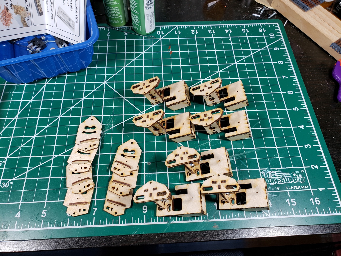
I needed to reverse the throw on half of them and I needed to support the control rods under the layouts so I designed and laser cut some supports and bell crank towers to use.
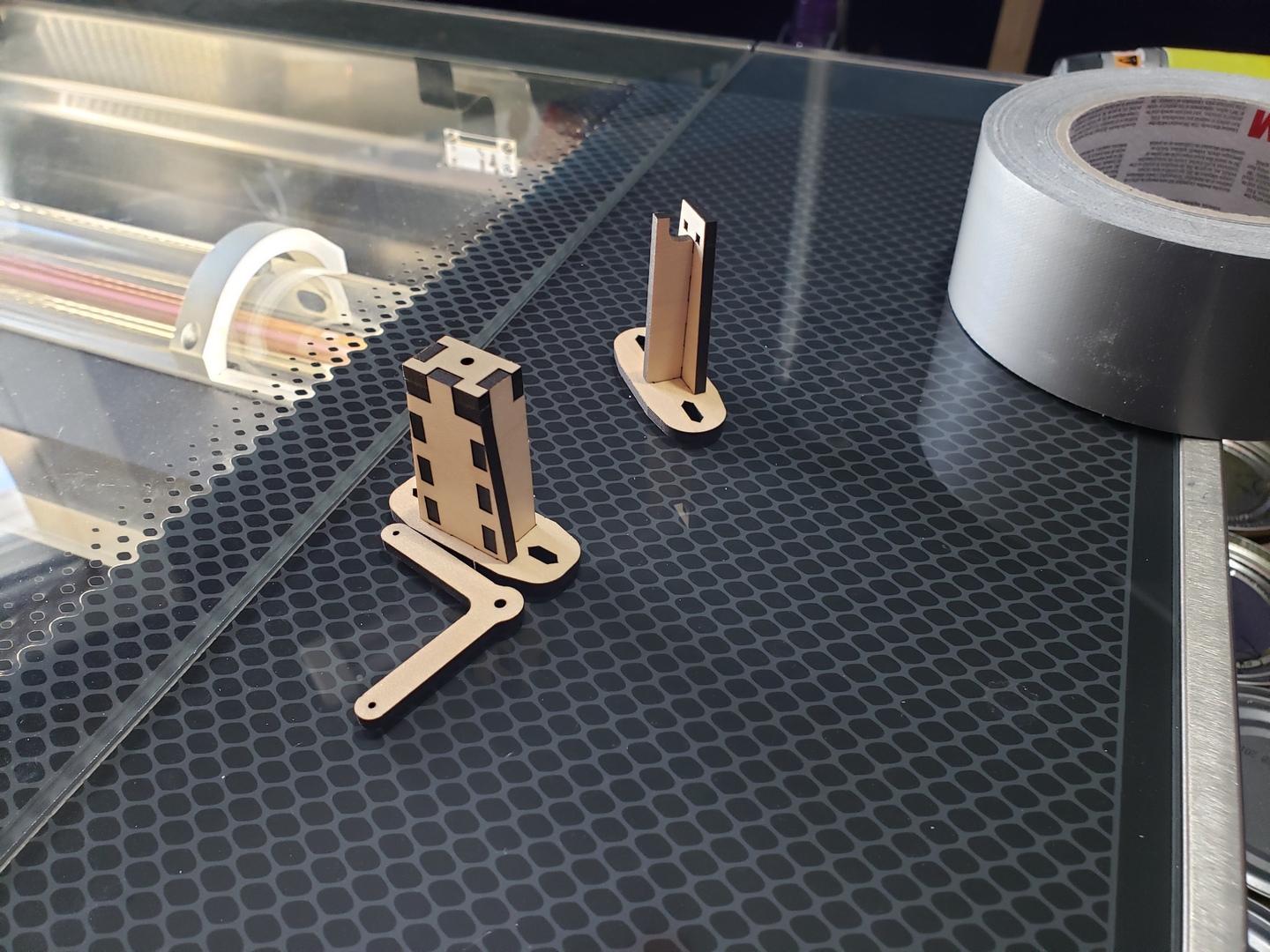
I’m not super happy with the support towers and I’ll probably redesign them for the next batch of installs, but this design did get it done. The bell crank towers worked just great though.
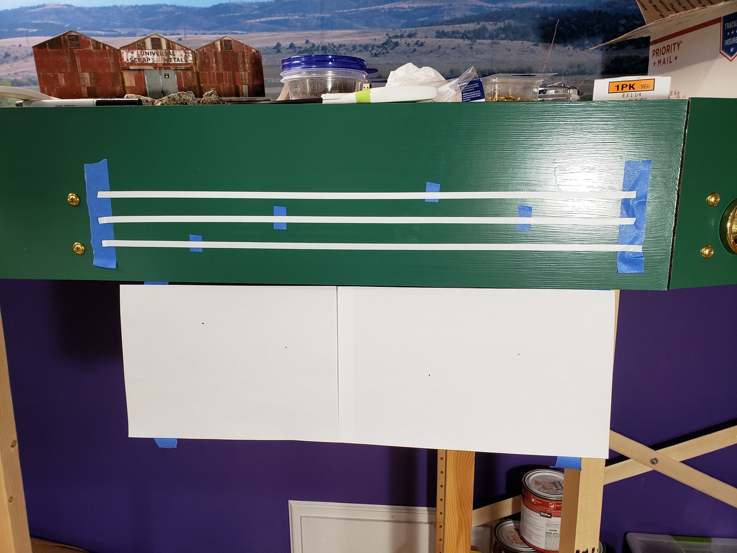
After installing the BullFrogs I needed to determine where the turnout controls were going to go on the fascia boards. I decided to order some 1/4″ white vinyl tape to make a track diagram with. I drew up some full size plans in LibreCAD and taped them to the fascia.
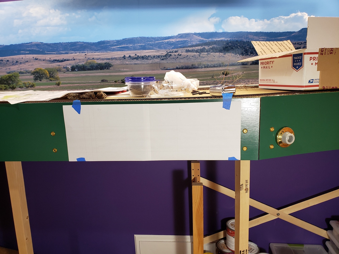
Then I used blue tape to mark the centerlines of the tape at the ends and center punched the control locations. Then I applied 1/2″ wide strips of blue tape where the center punche marks were. I ran the horizontal lines right across the tape and carefully trimmed the ends and cut out where the controls go.
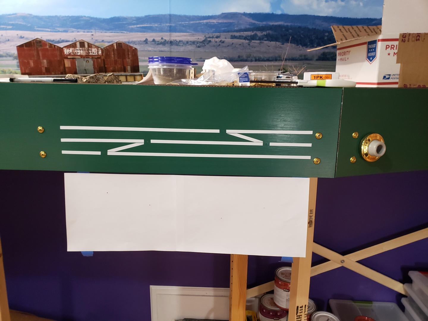
I added the diagonals by eye, trimming the ends to suit and then drilled the holes through the facia and benchwork with an 1/8″ bit.
I removed the facia panel and drilled the holes in the benchwork out to suit the control tubing with a 15/64″ bit (I think.)
Next up was to install all the tubing, supports and bell cranks. This was a bunch of seat-of-the-pants design-while-you-go work. Here are a couple of underside views. You can see two of the three turnout controllers where I had to route the cables through an L-girder and a couple of places where I had to use two bell cranks to turn the corner.
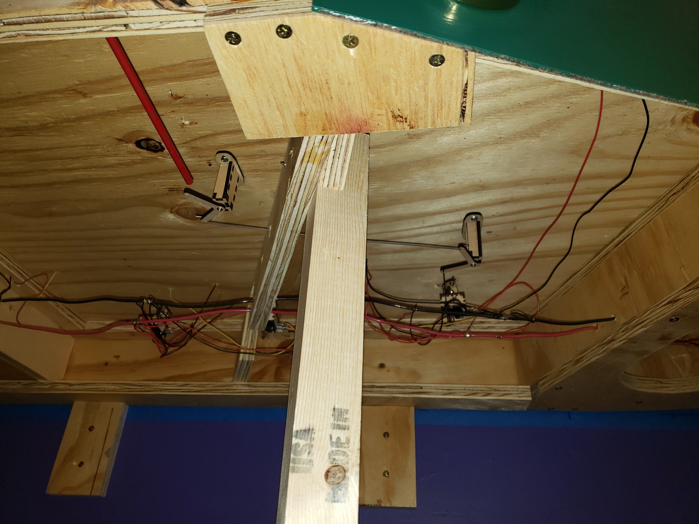
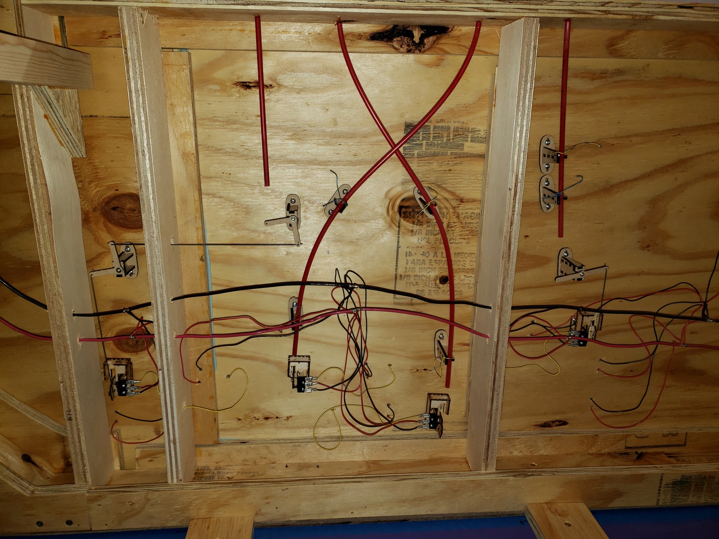
It looks kind of complicated, but it does work. 🙂
After getting all the tubing routed I removed it and roughed up the outside where I was going to use epoxy to attach it to the front of the layout and the supports. I glued it all in with 5 minute epoxy.
Then I drilled out the holes in the facia to clear the actuator rods and re-attached it to the front of the benchwork (hopefully for the last time.) Next was installing all the actuator rods in the tubing, attaching them to the controllers and bell cranks and cutting them to length.
The final step was to install the knobs. The knobs are just some wooden beads I found at the local craft store with 1-1/2″ 2-56 screws and washers.
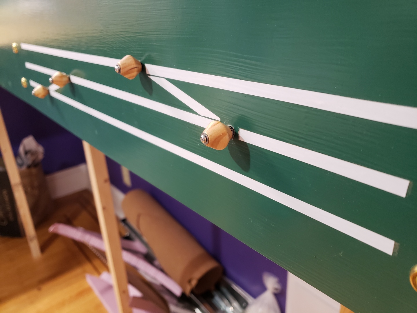
All the turnout controls work, and they all throw the correct direction – when all the knobs are pushed in all the turnouts are in the non-diverging route. Unfortunately testing with my diesel engine showed that the turnouts themselves need some work still. I’ll have to tweak those a little more to make them work better and I think I need to pull all the BullFrogs down and add heavier throw wires to them.
I’m also going to get some brass washers to put around the tubes under the knobs to make it look a little cleaner.
Oh well, it’s forward progress anyway.