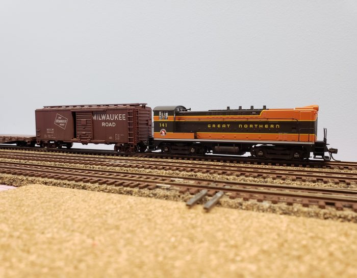
I went to a swap meet in May and one of the few things I bought was a new in box Stewart Hobbies model of GN Engine No. 141.
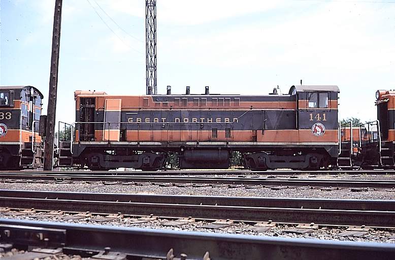
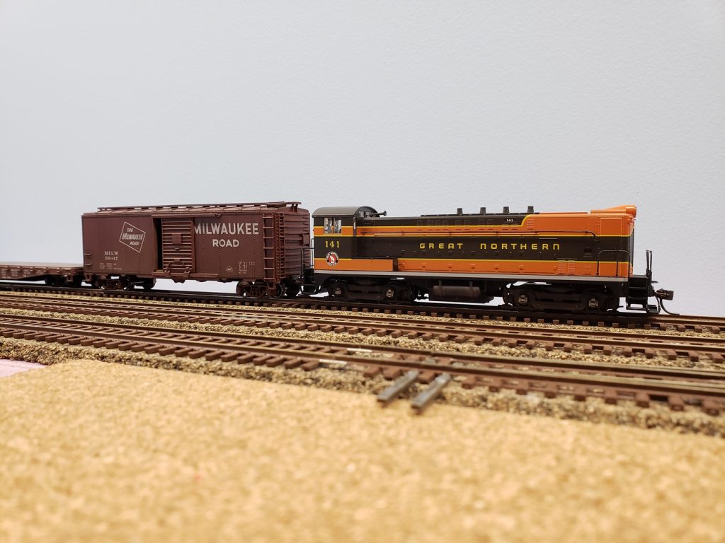
Engine No. 141 was a Baldwin VO-1000. The Great Northern purchased their first pair of VO-1000s in 1941 and their second pair in 1943. In 1944 the first four locomotives were renumbered to 132, 133, 137 and 138. Also in 1944 the Great Northern purchased six more VO-1000s and numbered them 139 though 144. The locomotives were delivered painted all black, but in the late 1940s they were repainted in the standard green and orange (as shown in the photo and as the model depicts.)
According to records, all the VO-1000 locomotives spent their time in the Twin Cities, but I’m going to ignore that and run mine anyway. Number 141 ran until it was sold for scrap in 1963, so it fits my time period.
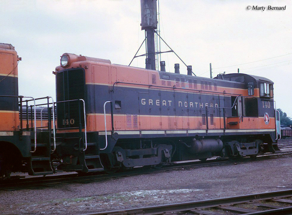
Bonus picture of sister engine no. 140.
The model appears pretty accurate and has nice detailing. Comparing the model to the photos it does appear that the prototype had some louvers on the access doors that the model is missing. I’ll leave adding those as a later project.
The model also has a NMRA standard 8 pin plug for adding DCC and the Bowser web site (Bowser bought Stewart Hobbies in 2004) has a quick how-to on adding DCC and a speaker to the model.
I ordered up a Soundtraxx DCC decoder and speaker in May, and then everything sat while I built the benchwork and turnouts for my layout.
Last week I laid most of the rest of the turnouts and track – up to the point where I need to figure out the bridges across Lutgens Creek anyway – and now I’m waiting to order the backdrops before I do anymore scenery. So I decided to pull out engine no. 141 to assemble it and add the DCC decoder and speaker. I needed something to run on all that new track after all!
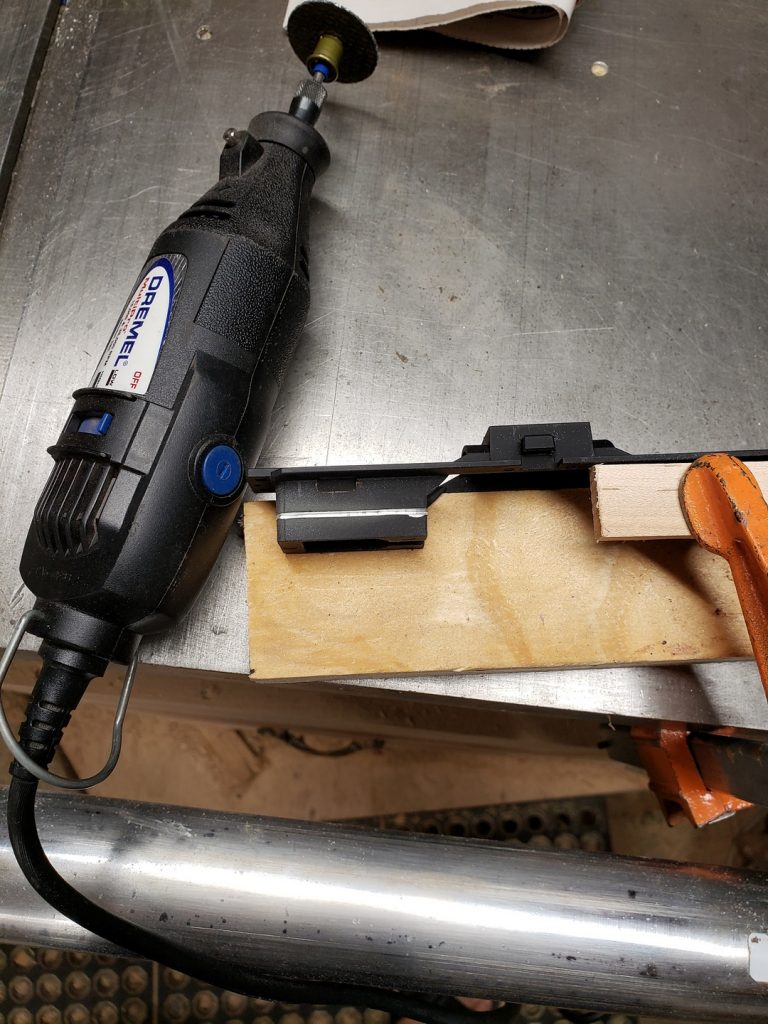
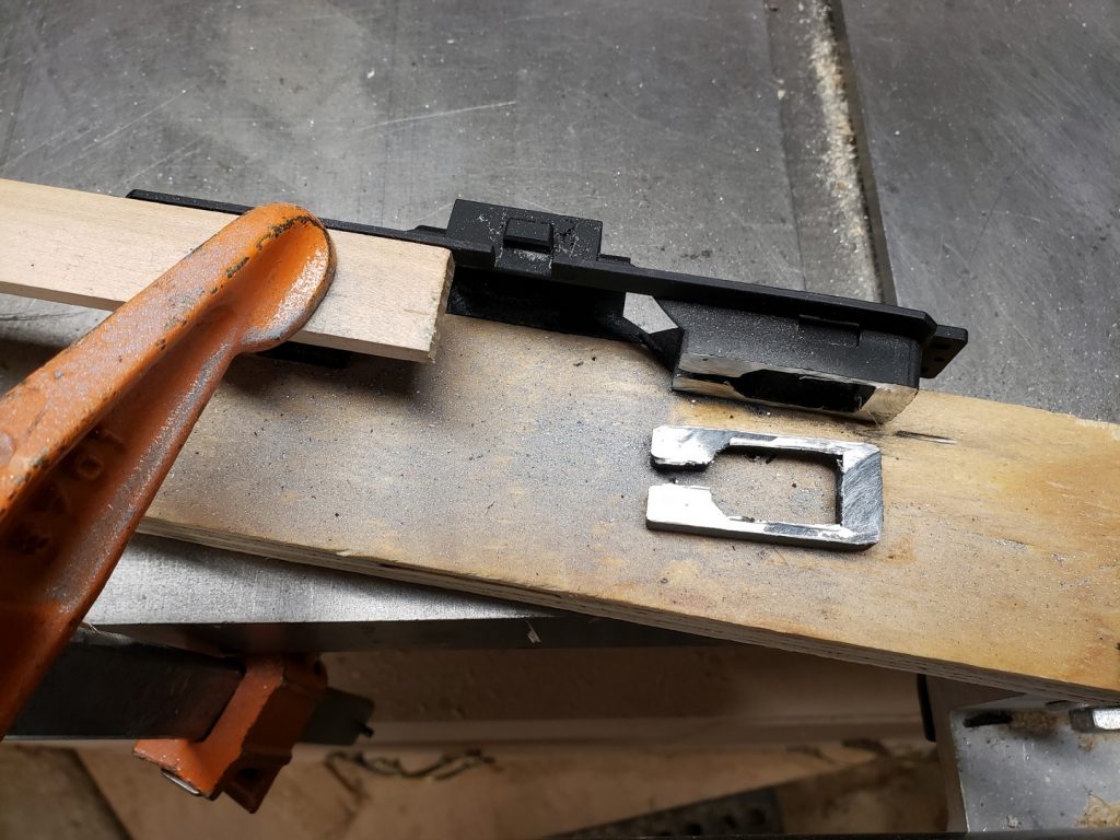
So the first step, of course, is to take it all apart so I can cut down the frame to make room for the speaker. The shell just pops off and then it’s pretty easy to remove the trucks. I also pulled the side frames off the trucks and the air tanks off the frame so I could do a little weathering on them.
I marked out the 1/4″ of material to remove and then headed down to the basement to use a cut-off disk in the Dremel to cut it down. It actually worked pretty well. A little clean up with a file and it was good to go.
I washed the truck frames and air tanks with some dish washing soap to get any grease off them and then blew them dry with some canned air. I set those aside and started adding the details to the shell.
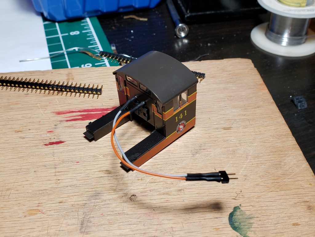
The pictures of No. 141 that I found online showed it had four short exhaust stacks which contradicts the GNRHS data sheet – apparently the first order of VO-1000 engines only had one stack, but it appears that the later orders had four. So I decided to go with the picture and drilled out the four holes and installed the stacks. Then I added the single horn to the center of the hood in front of the cab, as per the photos. I need to find a bell to install on the hood in front of the horn, and a “firecracker” radio antenna to add to the roof of the cab. I’ll probably add the all-weather cab window enclosures at some point too
I took a break from installing details and hit the air tanks and truck side frames with some Dull Coat. While that dried I worked on adding all the hand rails and grab irons to the shell. Unfortunately I managed to lose one hand rail (shot out of the tweezers never to be found again) and another one was not molded correctly. But you can still buy parts from Bowser, so I ordered some new ones. Had to buy the whole set, but that’s okay. The shipping cost more than the parts!
I added a little bit of rust to the trucks and air tanks with acrylic paint and reassembled them after they dried. I kept the rust light and can always go back to add some more if I decide that’s the plan.
I had to re-assemble the trucks and motor to the frame before attaching the speaker, since the speaker will block the access to the front truck.
When I bought the decoder and speaker I also purchased a “gasket” for the speaker (die cut foam with peel and stick on both sides) and some 8 pin NMRA plugs. I used the gasket to stick the speaker to the frame and then added some Kapton tape to hold it down a bit more firmly.
Next I soldered the wires from the decoder to the plug. That was a pain in the ass. I think I need to get a finer tip for my soldering iron. But I got it done and then soldered the wires to the speaker. I plugged in the 8 pin plug and used some more Kapton tape to mount the decoder and clean up the wires
I figured I’d better test it before I put it all back together. So I hooked up my controller (a Digitrax Zypher Express) to the layout, set the locomotive on the track and selected loco number 3 (the default setting for a new decoder.) The locomotive immediately started making the “start up sequence sounds” and then settled down to a nice lumpy idle! I flipped the direction lever to forward and turned the throttle up a little and the loco started moving in the correct direction. Great Success!
I tried to install the shell at that point only to discover that it didn’t fit. The 8 pin plug sticks up too high. Well that’s disappointing. I wanted to show off the loco anyway, so I fired it up again, but it failed to move! The sound worked, but not the movement. Damn.
I thought maybe I had fried the decoder by crossing some wires when pushing on the shell, or maybe one had broken, but it didn’t appear either thing had happened. So I looked up the warranty on the decoder. They come with a 90 day “we’ll replace it even if you blow it up” warranty! Great. I was getting ready to start disconnecting it and packing it up when I figured “why not reset it to factory defaults and see what happens?” So I did, and it fixed it! Stupid microprocessors. But at least now I don’t have to send it it.
After sleeping on it, I came up with a plan for making the decoder fit in the shell. Plan 1 was to just solder the decoder wires directly to the 8 pin socket. But then I came up with Plan 2! Plan 2 was to remove the socket from the circuit board and just solder the wires directly to the board. I grabbed my solder wick (super handy stuff to have around) and sucked up all the solder around the pins.
Unfortunately I could not manage to get the socket off the board. I spent about 20 minutes on it before I gave up and re-applied all the solder that I had wicked off. Oh well, back to Plan 1 then.
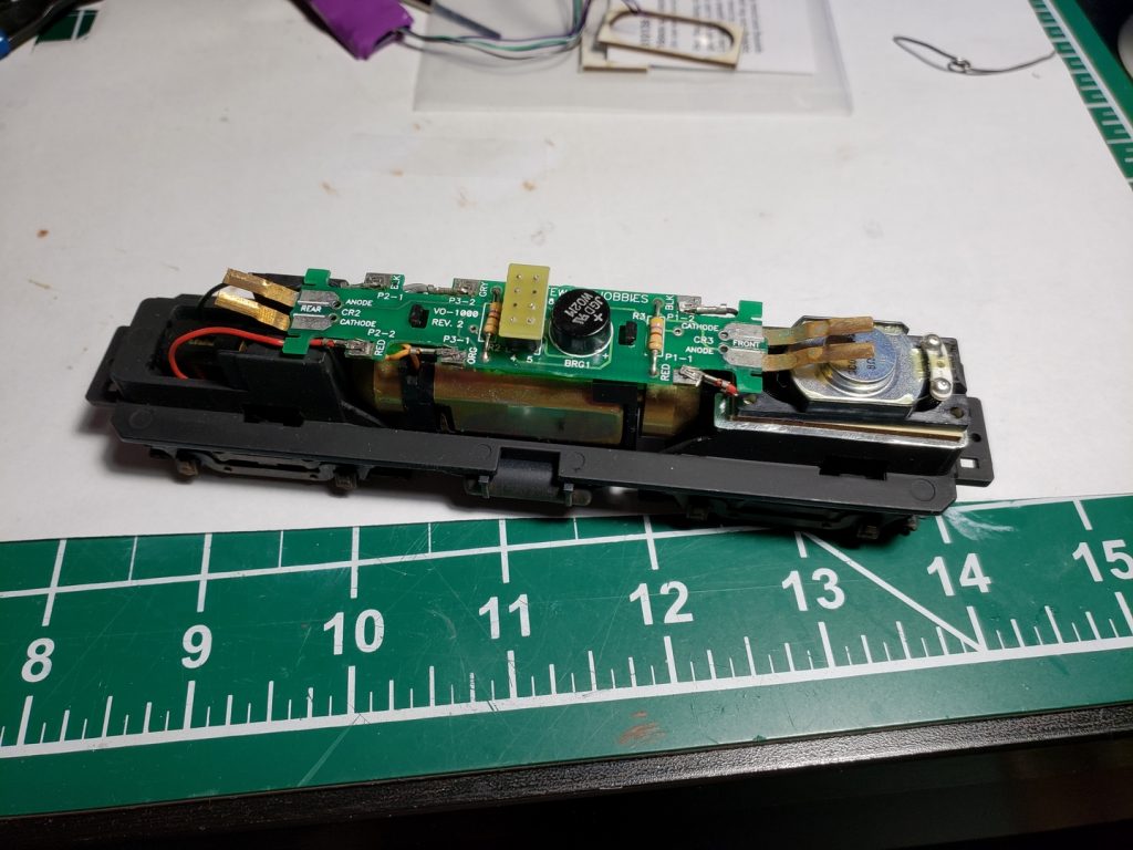
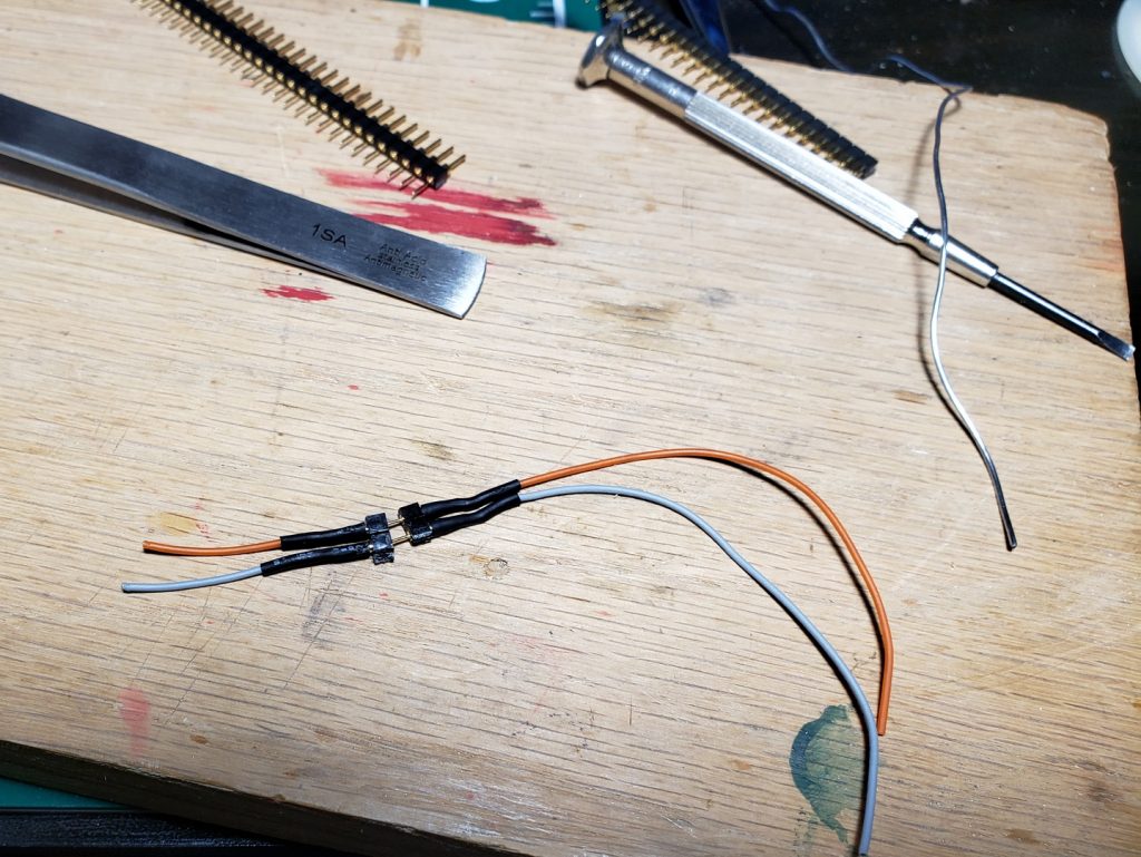
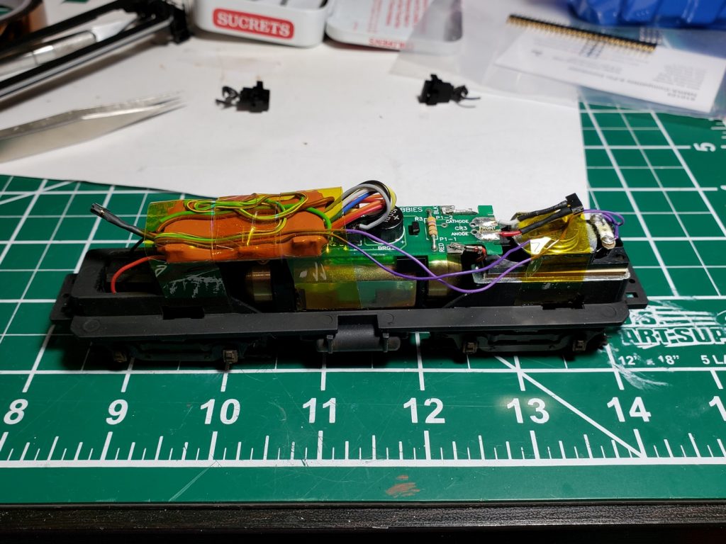
Before I soldered the decoder wires to the socket there was another thing I wanted to take care of. The connectors for the head and tail light LEDs were just copper strips that the legs of the LEDs contacted when the shell was assembled. This felt pretty hinky to me and the decoder would be in the way of the rear contacts. So I removed the copper strips and added some wires with plugs in them so I can still disconnect them when needed.
The plugs were made up of some pin and socket connector strips I purchased for this very purpose. They worked out pretty well too.
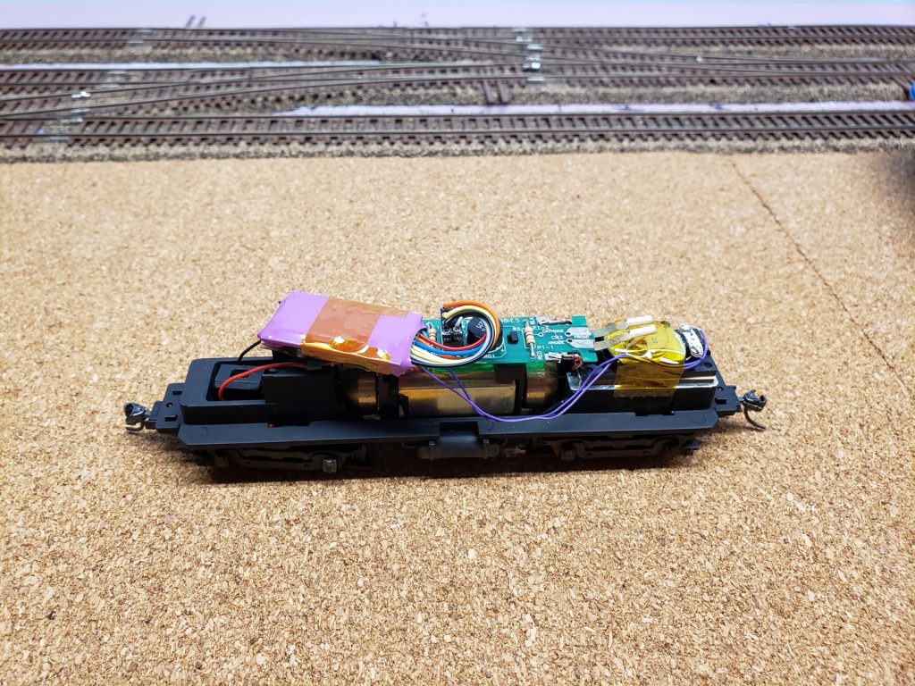
After sorting out the LED power, I soldered the decoder wires to the socket. This went pretty well as I had found my smaller soldering iron tip. After soldering the wires I cleaned everything up with more Kapton tape and decided to test it out before assembling the shell.
Great success again! Sound and movement both worked.
I tried to assemble the shell but there was still an issue with too much bulk under the long hood. After spending way too much time on it, I discovered that if I flipped the decoder over so the flat side was up, the bumpy side would fit down over some of the components on the circuit board and give me a little more clearance. This was the change that I needed and now it all fit back together properly.
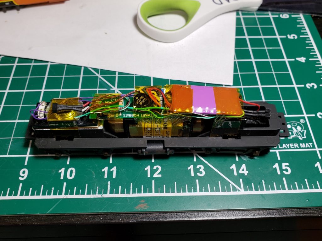
One more test run to make sure it still worked and we are golden. The head and tail light also work.
The last detail was to install the couplers. The coupler boxes are a major hassle to install. Especially with the Kadee coupler spring in there too. I got them installed once, but then had to pull them off again when the hood still didn’t fit.
Finally I gave up and bought some of the new Kadee couplers with the built in “whisker” springs so I didn’t have to try and keep the whole thing assembled while I put it into place. That worked out much better.
A glamour shot of the finished locomotive.
Here is a video of the locomotive starting up and running to cap this all off.